




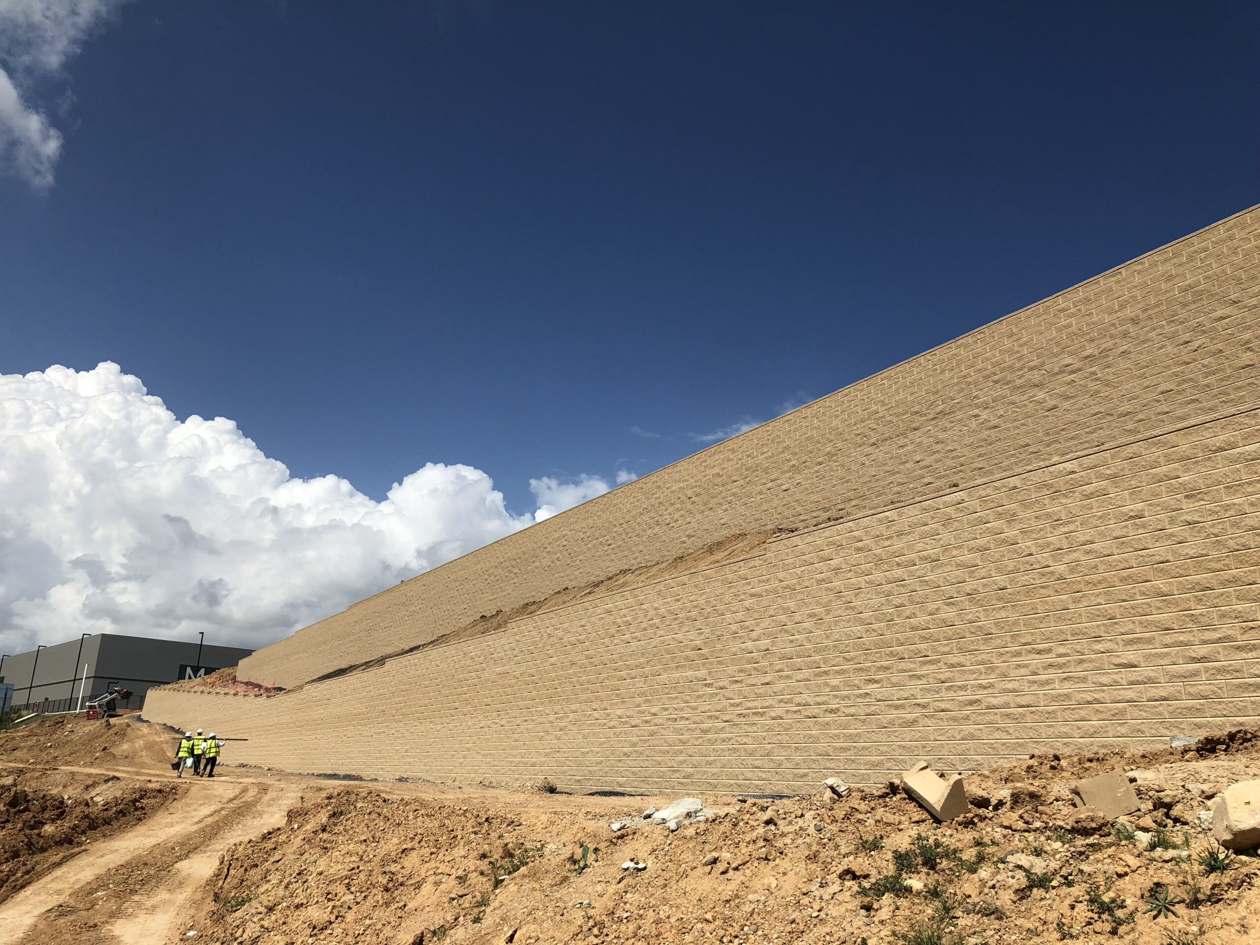
1. Planning: site assessment.
Before starting the installation of a reinforced soil retaining wall, we must check the geometry of the working area and the ground conditions behind and beneath the wall, as these will directly affect its stability. We must observe the physical characteristics of the site: the type of soil and its properties, the geometry of the wall and its surroundings. We will identify natural drainage lines, site boundaries, utilities, structures, vegetation, etc. The pressure behind a reinforced soil wall will vary significantly depending on the type of soil. In general, a wall built on clay will require more reinforcement than a wall of the same height built with gravel in sandy soils. 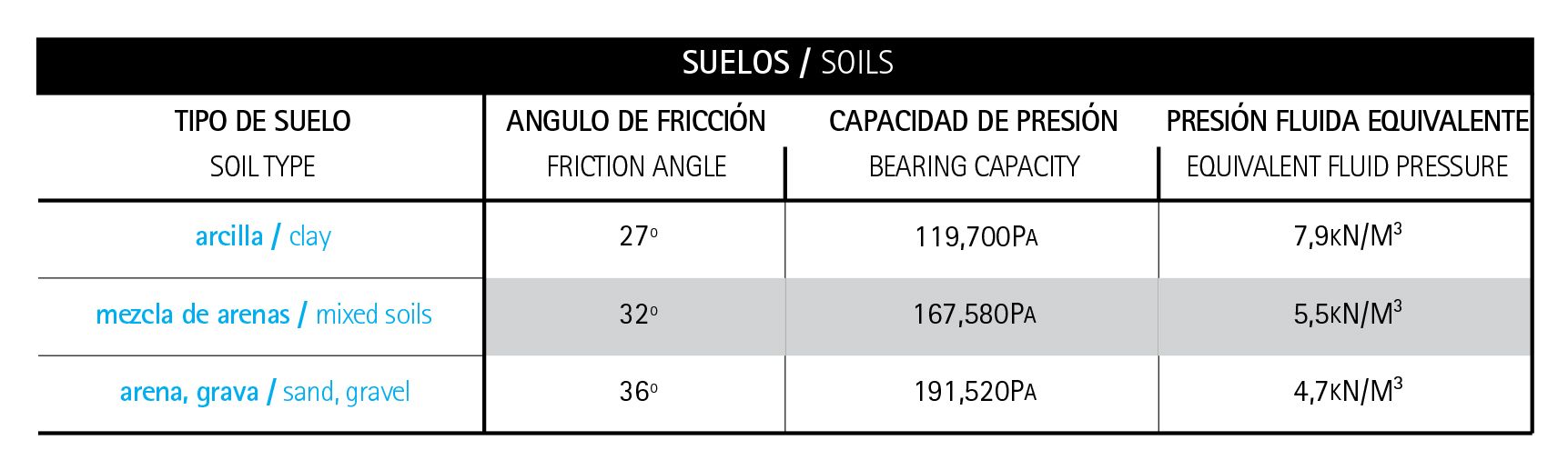
2. Planning: water flows near the retaining wall.
We must also carefully observe the main drainage lines and determine the flow and volume of any specific water source, such as roof drainage or groundwater. A slope plan should be developed to direct water around the wall, always within the possibilities of the work site. Channels should be placed above the wall whenever necessary to guide water movement. It is important to divert any concentrated water flow away from the wall, such as roof drains, drainage ditches or groundwater. Water accumulation above or below the reinforced soil wall must be prevented.
3. Design: a good design requires evaluating the following elements:
- Select the construction location: Minimize excavation and fill & optimize slopes and drainage.
- Define wall height and its geometry: Identify slopes above and below the wall & assess traffic or construction surcharges.
- Assess structural requirements: Determine whether it is a gravity wall or if geogrid reinforcement is needed.
- Calculate the overall wall envelope: Walls with higher inclinations (12º) require a larger envelope than walls at 3º or 6º, but require less geogrid reinforcement.
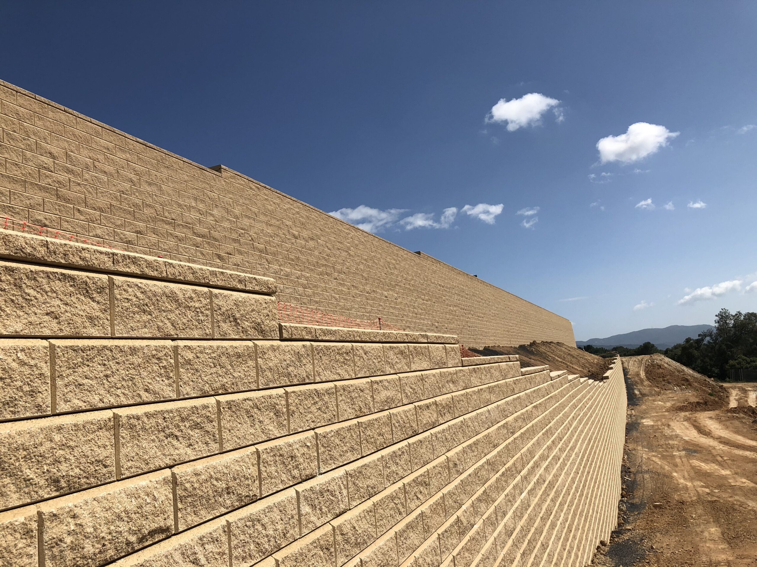
4. Preparation of the base of the reinforced soil retaining wall.
A trench will be excavated following the alignment of the wall. Its dimensions and depth will depend on the wall type. The trench must be deep enough, depending on the soil conditions, to allow it to be filled with concrete and to bury the required number of units. One block will be embedded for every 2.40 m of height.
It is essential to ensure a proper bearing base for the wall on firm ground. Calculations are made considering an allowable soil bearing capacity of 0.1 N/mm² (1 kg/cm²).
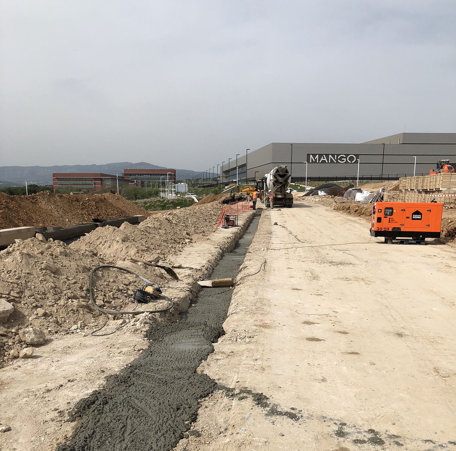
5. Construction: layout of the first course of units.
The first course of units will be laid on a dry mortar base, and the alignment of each unit will be checked side-to-side and front-to-back.
We will place the drainage pipe behind the unit and cover it with approximately 25 cm of gravel behind it. The internal cavity of the unit will also be filled with 12/18 granulometry gravel.
Another advantage of the reinforced soil retaining wall construction system is the positive connection between the geogrid layers and the concrete units. This connection is achieved thanks to the granular material (12/18 gravel) used to fill the internal cavities of the units. The larger the friction surface, the more the stress is distributed. The block wall becomes the facing and the reinforced soil mass becomes the structure. This interlocking between the unit (facing) and the mesh (reinforced soil) is called the “rock-lock” effect and is one of the best interconnection systems on the market.

6. Construction of the reinforced soil retaining wall.
Once the first course is in place, the rest of the backfill area behind the wall will be filled with soil from the site or imported material if necessary.
Once the backfill is placed, the soil is compacted using a roller compactor over a distance equal to the design length of the geogrid reinforcement. Mechanical equipment must be kept at least 1 metre away from the rear of the unit. Compaction is repeated at each course, i.e., every 20 cm, to achieve optimal compaction.
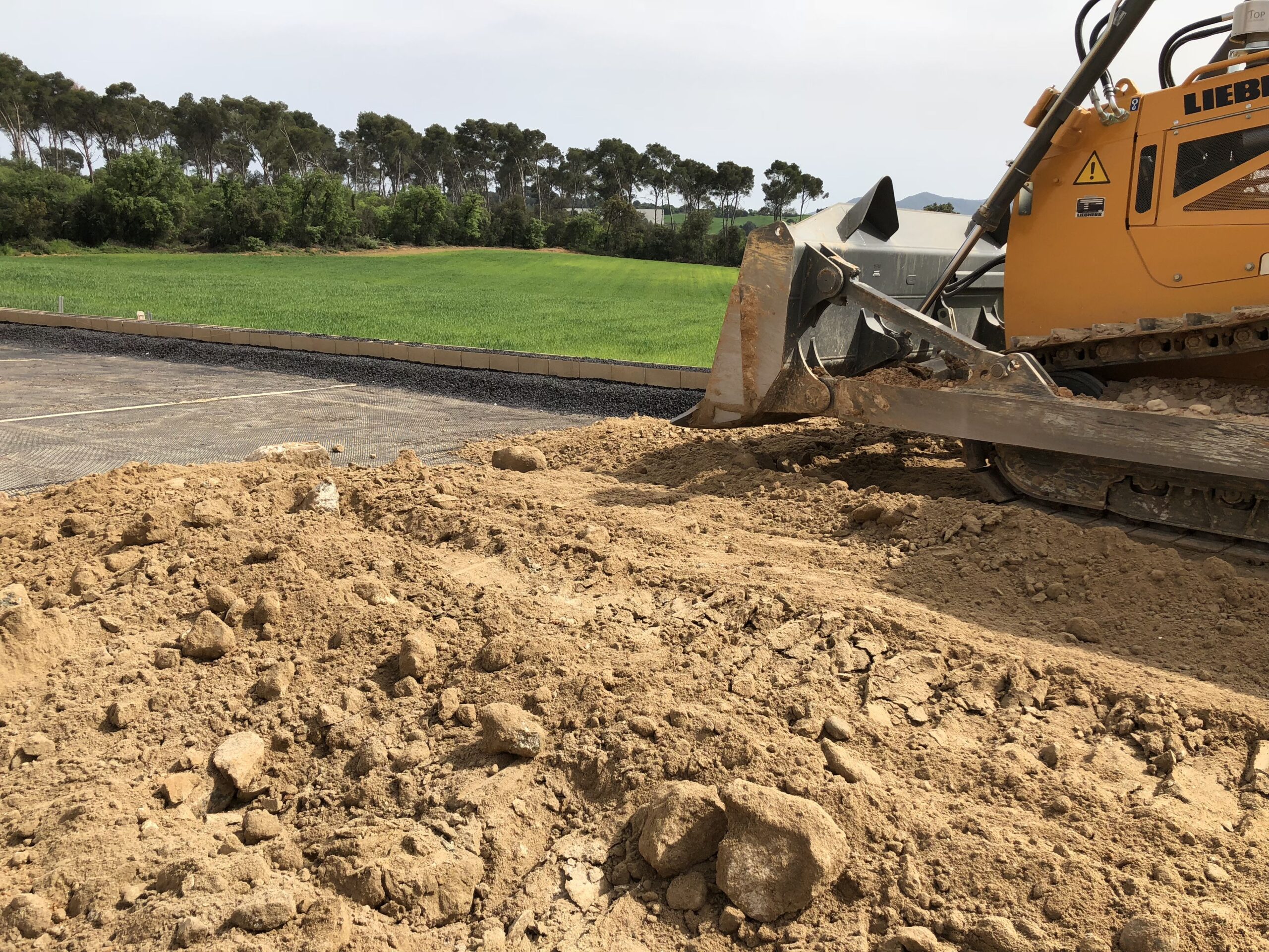
Backfill and compaction material for the wall: do not use a friction angle lower than 28º in large structural walls. Clay soils should be avoided, as they are the main cause of long-term wall issues. Clay soils continue to move over time, especially when they have excessive moisture.
7. Geogrid reinforcement.
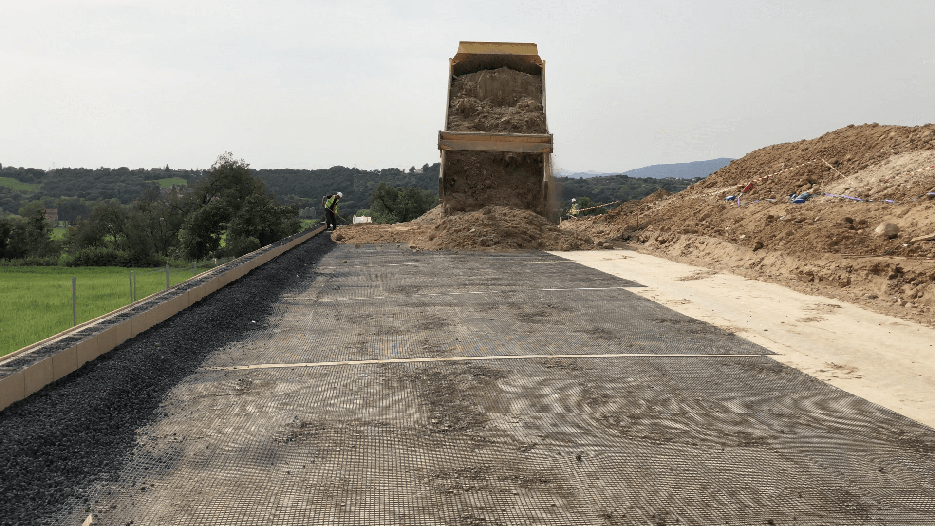
The geogrid reinforcement will be cut to the designed length and installed at the level indicated by the technical department calculations. The geogrid is placed over the unit and extended over the compacted backfill. The next course of units is placed over the geogrid and the unit cavities are filled again with gravel: positive connection.
The geogrid is placed from the unit interlock and laid over the compacted backfill. It becomes trapped between the facing units and the gravel used to fill them. The geogrid is made of high tensile strength polyester fibres, woven into a PVC-coated mesh. The length, strength, number of layers and spacing are key design parameters when constructing a wall.
The final geogrid layer: when there is a paved surface above the wall and a high level of compaction is required, the length of the last geogrid layer is increased by 1 metre. This prevents small cracks from forming between the compacted soil of the wall and the adjacent non-compacted soil.
8. Wall capping.
Wall capping is finished with an AB CAPS coping unit and a slope is created away from the wall to divert water. 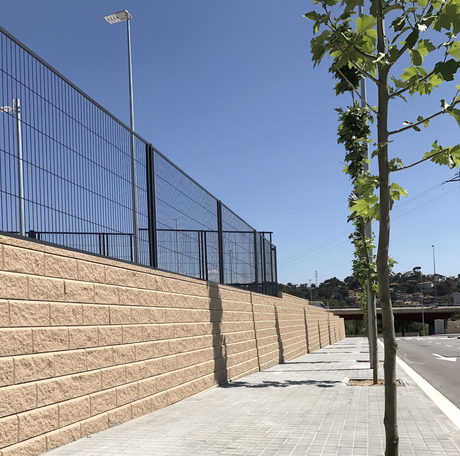
9. Curves and angles.
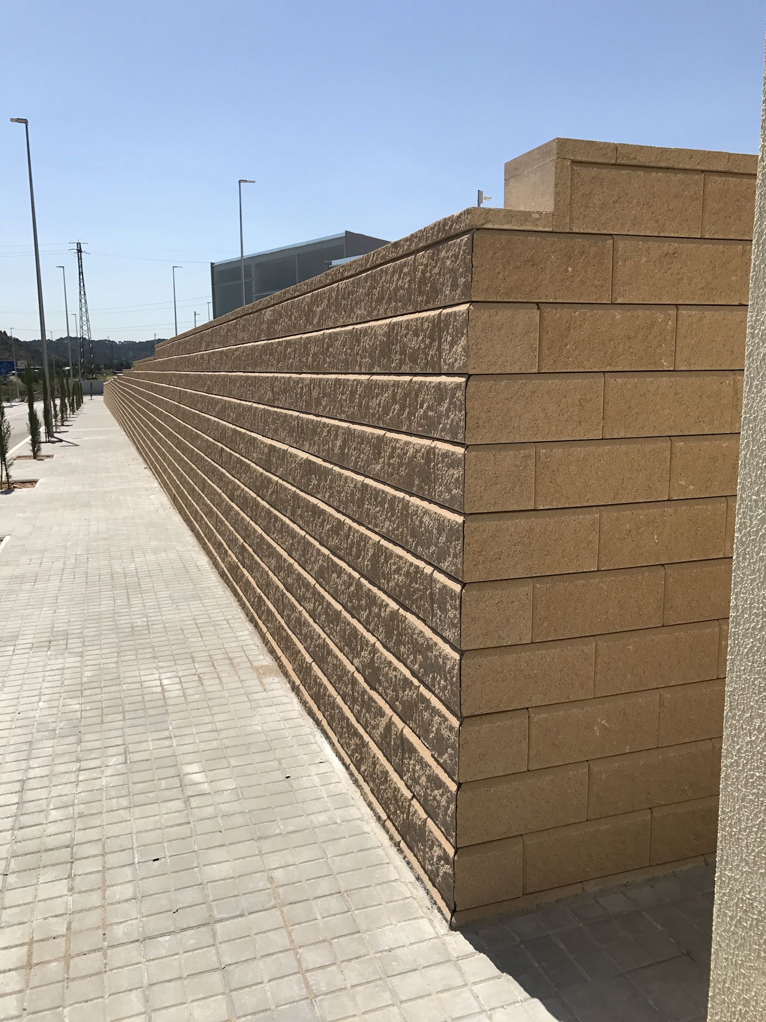
Curves: with this flexible wall system that adapts to the terrain, open and closed curves can be easily built. The minimum radius at the top of the wall is 1.5 m.
Angles: although curved lines are recommended, interior and exterior corners can be formed by cutting units to size.
Bibliography:
Allan Block Retaining Walls
BREINCO Reinforced Soil Retaining Wall Design Manual
